
AFTER COMPLETING MY electrostatic speakers and KEF/transmission line woofers, it became time to consider an amplifier for the ESLs. I had been using a Williamson "twin 20" driving some old output transformers (in reverse) with excellent results. A direct coupled amplifier offered a small, but perceptible improvement as demonstrated by direct sonic comparison with David Hermeyer's original high voltage, direct coupled electrostatic amplifier (see Issue #4, 1972 series, p.9). As this project was designed to offer the finest sound quality, I felt any improvement possible should be inclined. When I decided to use a direct coupled amplifier I had to face the problem of building one, of course. Unfortunately, Dave's original design was unacceptable to me. My reasons? It is physically just too huge, it wastes too much electricity, and it puts out enormous amounts of heat. My wife is not exactly keen on Dave's amp either, for all the above reasons and because she thinks it is ugly.
[Beauty is in the eye of the beholder, perhaps.--Ed.]
I affectionately nicknamed his amp "The City of New York," since in a dim room the tubes glow white hot like light bulbs and the neon lights flicker on and off--it looks like a city after dark. Dave tells me that a friend of his has named his version "The Monstrous Behemoth." I suspect some TM readers who have built this amp have named it worse things than that! At any rate, it was unacceptable, and I began a search for a class AB amplifier that would be much more efficient. Jim Walsh, a friend of mine, designed a unique class ABI direct coupled amp, but it required output and driver chokes. It appeared quite difficult to build with hand wound chokes and probably somewhat higher distortion than Hermeyer's design.
I discussed the situation with Dave and he (as always) was most helpful. He suggested a smaller tube with either reduced voltage or current, resulting in an amplifier both smaller and less wasteful of heat. I took a series of voltage and current measurements under dynamic conditions playing music through my speakers. I determined that although I would need the same voltage, I could reduce the current by 50% and still not clip the amp on my system at 100dB peak SPLs as measured from my listening seat about 5 meters from the speakers. This is considerably louder than concert hall level, and sounds much too loud to me. It gave me assurance that I had enough power to play any music I might wish at any level I might wish without clipping thi amp at any time. I made my measurements by calibrating an oscilloscope to 1.4 times the voltage (or current) as related to sine waves being measured on a VTVM and then watching the scope while music was played. I found I needed 2kV at slightly over 25ma. Note that these are peak, not RMS values.
As Hermeyer's amp used 55ma of plate current, it was clear that an identical amplifier could be built which could operate at the same 2.2kV with 50% of the plate current (27.5ma). I chose the cheap and effective 8068 tube, made modest changes in the amplifier circuitry to handle the slightly different tube parameters, and built my prototype.
It worked exactly as I expected with no problems at all. My Son of Behemoth amplifier weighs 57 pounds, compared to Dave's 105. It is much smaller, about the size of an Audio Research D-76 or a Crown DC-300a. It fits a standard 19" rack mount panel, 8 3/4" high and 10" deep. Most important, rather than dissipating 900 watts, my unit dissipates a mere 290. This is roughly equivalent to a tube amp of about 60 watts per channel.
I do not have the necessary test gear to measure the performance of the amp, but I expect it to be equal to, or slightly better than the original design, for reasons I believe will become clear further on in this article. Sonically it is superb, with the most noticeable improvement over my transformer coupled drive being a much tighter and more detailed midrange and upper bass. The total sound is slightly smoother, free from grain, and a subtle veil is lifted from the sound.
Construction
Please refer to David Hermeyer's original articles on the basic design and construction of his amp (Issues #4, 1972, and 3, 1973).
Fig.l is my revised schematic.
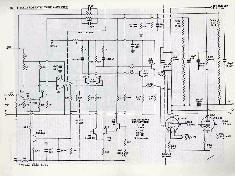
1. Use 8068 beam pentode output tubes, rated at 3.5kV at 35 watts. These are normally used as high voltage series regulators and cost about $5.30 each (the original 813 costs about $35.) The 8068 uses a standard 8 pin octal socket which cost less than 50¢ each.
[Use porcelain types for safest operation. --Ed.]
2. Each filament requires 6.0 to 6.3V AC @ 0.9 amps. Little 6.3V AC transformers are easily obtainable, but I chose to use the standard Triad (#F34A) transformer which has four separate secondaries rated at 6.3V AC @ 1.75 amps each. The transformer costs about $12 and is about the size of a cube with 3" sides and comes with end bells standard. I have seen these surplus
although I had already bought mine new. No rectification or balancing resistors are needed; just connect the secondaries directly to the tube socket terminals. My amp has absolutely no audible hum, or any noise for that matter.
3. The 8068 is 4 5/8" tall, 4" seated, 1 9/16" in diameter, and has an indirectly heated cathode. Connect as per schematic. The 2700, lW cathode resistor may be carbon type.
4. Grid 2 (screen) should be +200 V DC with a 100ma supply for four tubes. As this 100ma is not being drawn constantly I opted to use a 25ma continuous rated supply and have had no trouble with it overheating.
5. Instead of two 250K series resistors rated at 5 watts (metal oxide film types) as the feedback loop attenuator, use ten 50K (47K is fine) resistors in series rated at 1 watt. These should be identical metal film types. The reason? Reduced distortion. As Dave explains it to me, resistors have a voltage coefficient (similar to a temperature coefficient) which makes them non-linear if they have a high voltage drop across them. Carbon is the worst in this respect and metal oxide film is the best (but not perfect). Splitting the voltage drop across many resistors minimizes this effect. In my amp, each resistor drops a maximum of 220 volts. As the feedback to the input must accurately reflect the output signal, great linearity is obviously required for maximum performance and lowest distortion. This is one reason why I believe the performance of my amp may be better than the original design.
6. Metal oxide film resistors in locations with asterisks on the schematic will also improve the performance.
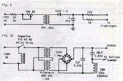
Fig. 2
7. Change the plate resistors to 40K at about double the power rating required. They will dissipate 30.25 watts each. I used 65W flat wound types and the stack of them dissipates 121 watts, and they really get hot! I did not want to use a fan in the amplifier, so I mounted them out in the open so they could cool well. As a precaution I mounted them on insulating washers. I found the standard spacers used for mounting power transistor bolts to be ideal as they insulate the inside of the hole drilled for the bolt as well as the head and nut of the bolt. I just used standard spacers for mounting all the resistors on the same bolts. I knew that at idle all the resistors would be at the same voltage potential (2200V DC at one end, 1100V DC at the other). With high level signals I surmised that the maximum 2.2kV difference between them at one end
might cause them to arc or conduct to the bolt. I did not insulate them further, however, and have had no arcing or shorting problems. I used flat resistors for high density packing. Their 100pF shunt capacitor is changed from the original design's 200pF--note schematic.
8. The original +100 volt supply for the circuit board drive components is now reduced to +80 volts. The same semiconductors are still used, so the drivers do not get so hot (although the small heat sinks are still necessary). I had a great deal of difficulty finding a small transformer to use in this supply. Only 100ma is required (8 watts) and as space was critical I wanted a transformer that was just big enough that would be in the range of 60 to l20V AC. I finally gave up, took a small 6.3V AC filament transformer apart and rewound it. I had never wound a transformer before, but I followed the directions in the latest edition of The
Radio Amateur's Handbook and it worked perfectly. (All TAA readers should consider this book an absolute must for their reference. It is a virtual goldmine of information and will answer almost any question you may have about practical electronics.) I wound it for 63 volts and used a full wave bridge with capacitor filter for an unloaded voltage of about 88V DC. Under the constant load of the driver transistors the voltage remains constant at about 79V DC. The small transformer fits under the chassis (Fig.8).
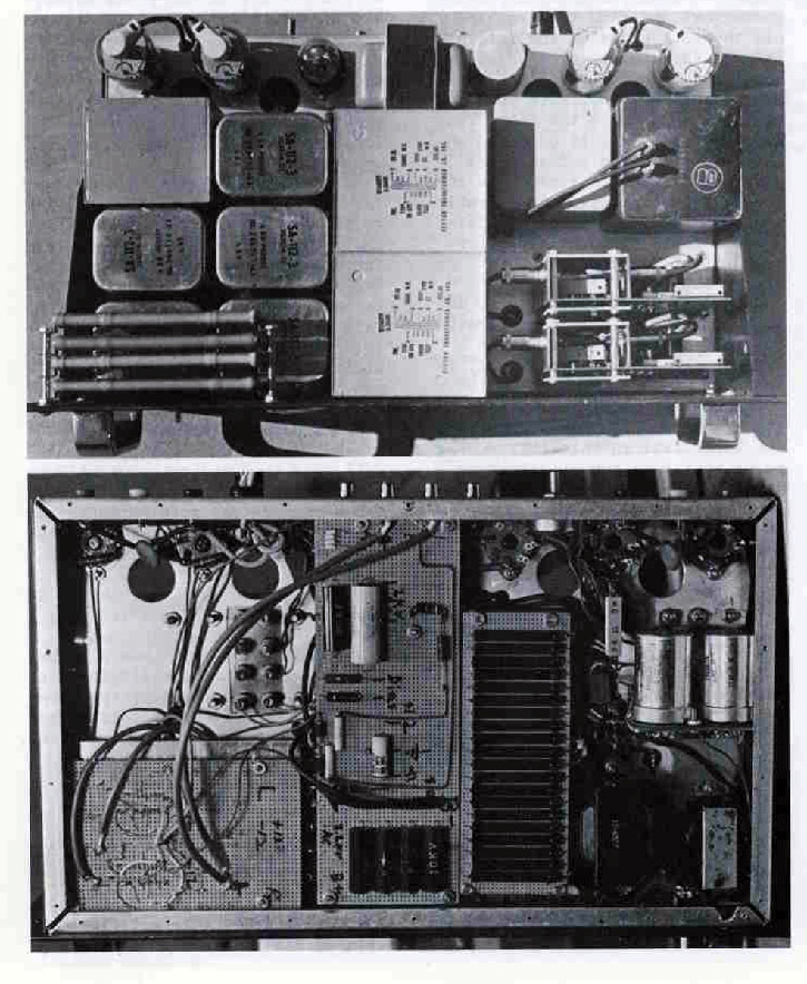
The other transformer seen there is for the 12V DC power supplies. All the other transformers I used were surplus military hermetically sealed units. I love quality, and besides, they look so nice! I was lucky enough to find a 2kV sealed unit @ 20ma for the bias supply, but if I hadn't I would have wound a tiny, high voltage transformer exactly as I had done the 63 volt unit, and I would have used a voltage doubler or tripler to get the necessary voltage (2kV of bias is plenty). To avoid the large 5 watt pot used to regulate the voltage of the bias supply, I used a standard pot in series with a fixed wirewound, 5 watt resistor. This required one resistor change to get a suitable value, but it works fine. Connect it as in Fig.2. By using a completely series connection (as opposed to paralleling one resistor across the line as shown in Dave's original article) there is even less current drawn through the t watt pot and it does not even get warm.
9. The big B+ power supply in Dave's original amp seemed too complex and unreliable because of all the parts required and because of all those perishable electrolytic capacitors, making it too big. So I turned to the trusty Radio Amateur's Handbook and designed a different power supply. Right off I' noticed that with all those 500vF capacitors in series, Dave achieved a total of only 62.5 vF capacity! Not really very good filtering, although obviously adequate. I was determined to do better than that. The string of capacitors would have to go, and more reliable ones rated at the full power supply voltage would have to be used. I ended up using 7vF oil capacitors rated at 2.6kV. I chose a reactor filter so would not need high capacity but would still achieve superb filtering (Fig.3).
 I used one capacitor at the input, followed by the reactor, followed by four capacitors in parallel to get 28vF following the choke reactor. Note that the reactor is in the negative lead so it does not see the high voltage on the positive side of the supply. This virtually eliminates the possibility that the choke will develop a high voltage short to its core since it is only 60 volts above ground in the negative lead. It is not at ground potential only because the negative lead is connected to the high voltage common of the amplifier per Dave's original schematic. Just to be safe, I chose a reactor rated at l500V AC! I also used 25 Henrys of inductance which is far more than necessary as about six would be fine. Pardon me for being conservative, but things work better and longer that way. I would not expect this supply ever to fail, which is not something I can say about electrolytic capacitors. I used a pair of military transformers rated at 900 volts at l20ma in series for l800V AC. They are exactly as big as necessary for the supply which must deliver 110ma @ 2.2kV (242VA). These transformers are conservatively rated and also have a 5 volt @ 3 amp filament supply which is not used and gives a further margin of safety. In operation the transformers reach about 130 0 F which is quite reasonable.
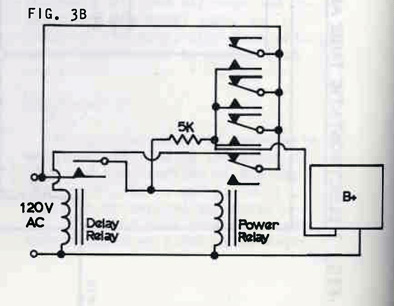
Lastly, I wanted to eliminate those strings of diodes for the high voltage rectifiers. I was able to locate surplus 10kV @ 1 amp (conservative again!) diodes for $14 per four. These can be obtained from Electro-Science Mart or B & F Surplus. My oil capacitors were new and cost almost $10 each from Electro-Sales. These oil capacitors are quite small for 2.6kV units @ 7vF but have the disadvantage that their contacts are metal straps with one connected to the case. Therefore they must be insulated from the chassis. I took four of them and soldered them to each other (the fifth is on the other side of the reactor). I drilled a piece of 1;" Plexiglas to accept the metal straps from the center of the capacitors. Then I punched chassis holes considerably larger than those in the Plexiglas so the Plexiglas formed an insulating ring when the capacitors were mounted with their tabs extending through the chassis. I glued the capacitors to the Plexiglas with 24-hour epoxy and attached this strong, rigid assembly to the chassis with bolts. Capacitor connections were made with high voltage test prod wire. I placed an Amperite 45 second delay relay in the AC line to the B+ transformers. This delays the B+ automatically until the 8068' s heaters get hot. This also allows easy testing since removing the relay tube from its octal socket makes the B+ inoperative. I quickly discovered that the B+ load ate delay relays in the ESL amp. The solution was to add a relay that was operated by the delay relay (see Fig.3B). I set it up so that three of the four contacts (rated at 3 amps) are paralleled for handling the B+ with the fourth contact used to disconnect the delay relay power so that it resets and the full delay is obtained should the amp be rapidly switched on and off (kids). I used a Potter and Brumfield 4pdt relay with a l20V AC coil. The 5K resistor keeps the delay relay contacts from delivering significant current to the Issue 1/1976 15 B+, but allows enough to keep the secondary relay pulled in after the delay relay contacts open. The system is now an "all or none" system: it either turns on or it doesn't.
Comments
The large oil bias supply filter capacitor in Dave's original amp need not be so elaborate. I used a much smaller O.l~F mylar capacitor rated at 4kV. Frankly, since the speaker itself is a capacitor it is not necessary to use even that much capacity. I suspect (although I have not tried it) that no capacitor at all would work o.k. My amplifier worked correctly from the moment I first turned it on (but you can believe I didn't enjoy that 45 second wait until the delay relay turned on the B+!). I have, however, had considerable trouble with associated equipment when driving this amp. To begin with, the amplifier is designed to be driven by a low impedance current source. Since you can't get DC current through a capacitor, this rules out all AC coupled equipment --which is virtually every commercial/audiophile type low level component on the market.
Although the amplifier can be made to operate from such a source, you will not be able to get the 500 volts of offset out of the output and this will seriously impair the efficiency and SPL of your speakers.
As a solution, use a current source buffer amp which might as well be an electronic crossover. I currently am using Old Colony's electronic crossover with satisfactory results, but whatever you use must have plus and minus "balanced" power supplies and must not have an output coupling capacitor.
Another problem with associated equipment is oscillation. Exactly why the amplifier should cause other equipment to oscillate is unclear to me. In any case, the amplifier is completely stable when driven by some equipment, and very unstable when driven by other equipment. The instability ranged from "motor boating" or high frequency squeal to just crackling or chirping on loud, high frequency transients.
I did obvious things like changing grounds around and adjusting shielding, but this never changed anything, so apparently this was not the problem. Close proximity of the amp to its associated gear did aggravate the problem, and I keep the amp six feet away from anything else. I found two ways to improve the situation. The most effective is to add series resistance to the input of the offending component. In my case this turned out to be 10K at the input of the Old Colony crossover. Another trick was to add a capacitor across the output of the component so that the high frequency bandwidth is reduced.
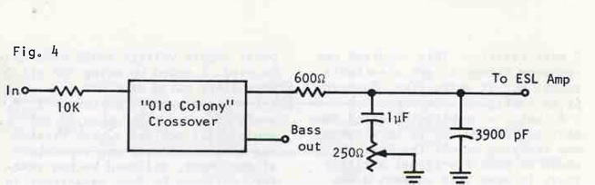
Fig. 4
In the case of the Old Colony crossover I found that a 3dB corner of 68 kHz worked very well. In addition, a 600n resistor should be added to the output so that the output impedance is stabilized and the amp output can be stabilized for essentially zero offset. I also added some equalization components (detailed in Issue #4, 1975 series, pp.24 ff.) boosting low frequencies to compensate for the phase cancellation at low frequencies and beaming effects of the speaker.I am currently using 12dB/octave crossovers and find that rolling off the ESLs at 240Hz and rolling off the KEF woofers at 120Hz is about right. Using identical crossover points does not work well in this system because the ESLs' fundamental resonance is bringing up their level in the crossover region, which when combined with the woofer output gives an undesirable and annoying peak in the mid bass. I would guess that the effective subjective crossover point is around 150Hz. I have more experimenting to do in this area. It will be interesting to see what faster ICs and steeper slopes do to the sound, for example. The amp was carefully designed to stay cool, and I'm pleased to say I was successful in this regard. The plate resistors run at extremely high temperatures, so I kept them completely away from everything else and out in the open so they wouldn't conduct heat to the chassis. I didn't want to use a fan, so I mounted the tubes on the extreme edge of the chassis and punched 1" holes completely through the chassis for free air flow. The tubes do not seem to get excessively hot and can even be touched for a second or two without burning you. The power transformers in the B+ supply gradually heat up the whole amp, hut it never gets more than comfortably warm except on the transformers themselves. I also did not use a perforated cover on the amp because the tubes and plate resistors would greatly heat this, making the whole amp very hot after a time. I decided instead to use sealed components and have all high voltage wiring under the chassis. As the components are rather heavy for an aluminum chassis which looks like Swiss cheese after cutting the mounting holes, I used a h" aluminum bottom plate which is secured every 3 inches with a screw as you can see in the photo below.
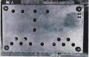
The k" steel front panel adds more rigidity. My fears that the amp would be underpowered were completely groundless. I can produce levels greater than l06dB at my seated location roughly 15 feet from the speakers. Although the original directions for adjusting the output voltages to lkV are not exactly correct, they will work just fine. Ideally, for highest efficiency and maximum SPL you should precisely split the B+ power supply voltage in half. This will allow the maximum voltage swing in both directions and will allow the diaphragm to be the maximum distance from the stators so that the highest possible bias supply can be used for maximum efficiency. If you use my supply you will find the correct value will be 1100 volts. Be sure to let the tubes warm up for a few minutes before making this adjustment, and be sure to adjust the DC offset out first. The DC offset is rather touchy as you approach the correct setting. I found a 10 turn precision pot mounted on the circuit board to be vastly superior to the single turn pot usually used. Lastly, the tubes are run at about 86% of their rated dissipation and should have a life of at least 5000 hours.
SUPPLIERS
Electro-Sales, 1.00 Fellsway West,
Sotrervi11e MA 02145 (Oil capacitors
Catalog $1.
Electro-Science Mart, 119 Foster St
Peabody MA 01960 (HV rectifiers,
Catalog available.}
![]() Build a hybrid tube amplifier to drive electrostatics (1976) as published in The Audio Amateur magazine
Build a hybrid tube amplifier to drive electrostatics (1976) as published in The Audio Amateur magazine